Guitars, Microchips, and Assembly
My first attempts at programming were writing hacky embedded C++ to run Arduino microcontrollers, brute forcing my way through compiler errors to try to make LEDs blink and motors spin. These days I write most of my code in high-level, dynamically-typed languages, but there’s still something alluring about that intersection of software and hardware - about watching your code run in the physical world.
So, leaving behind the comfort of high-level abstractions and garbage-collected memory management, I spent a few days diving back into the world of low-level embedded code by building a guitar effects pedal around the FV-1 chip. Because what’s lower level than Assembly?
A Quick Intro to Guitar Effects
Guitars make sounds1. Sometimes you want those sounds to be different. Throw the sound at a transistor until the transistor stops working right and you get distortion. Use the sound to shake a spring and listen to the other side of the spring and you get reverb. Pass the sound through a conductive liquid that’s rocking back and forth to modulate resistance and you get tremolo. These are analog effects. No code, just physics.
We’re programmers, not electrical engineers, so what about digital effects? Pass a sound through a special type of computer called a digital signal processor (DSP) that’s designed to run at a fast, consistent clock speed, and you can get all kinds of effects using software instead of hardware.
The Hardware
Okay, we do need some hardware. The FV-1 is a chip designed for guitar effects like reverb, delay, and compression that’s found its way into a bunch of high-end pedals because it’s cheap and flexible. That popularity has led to open source tools, premade programs, and development boards that make it much easier to get started for a DSP beginner like me.
I picked up a development board (chip included), some EEPROM chips to store programs, and a handful of resistors, capacitors, ICs, and switches, and spent a morning soldering the kit together into a working2 pedal.
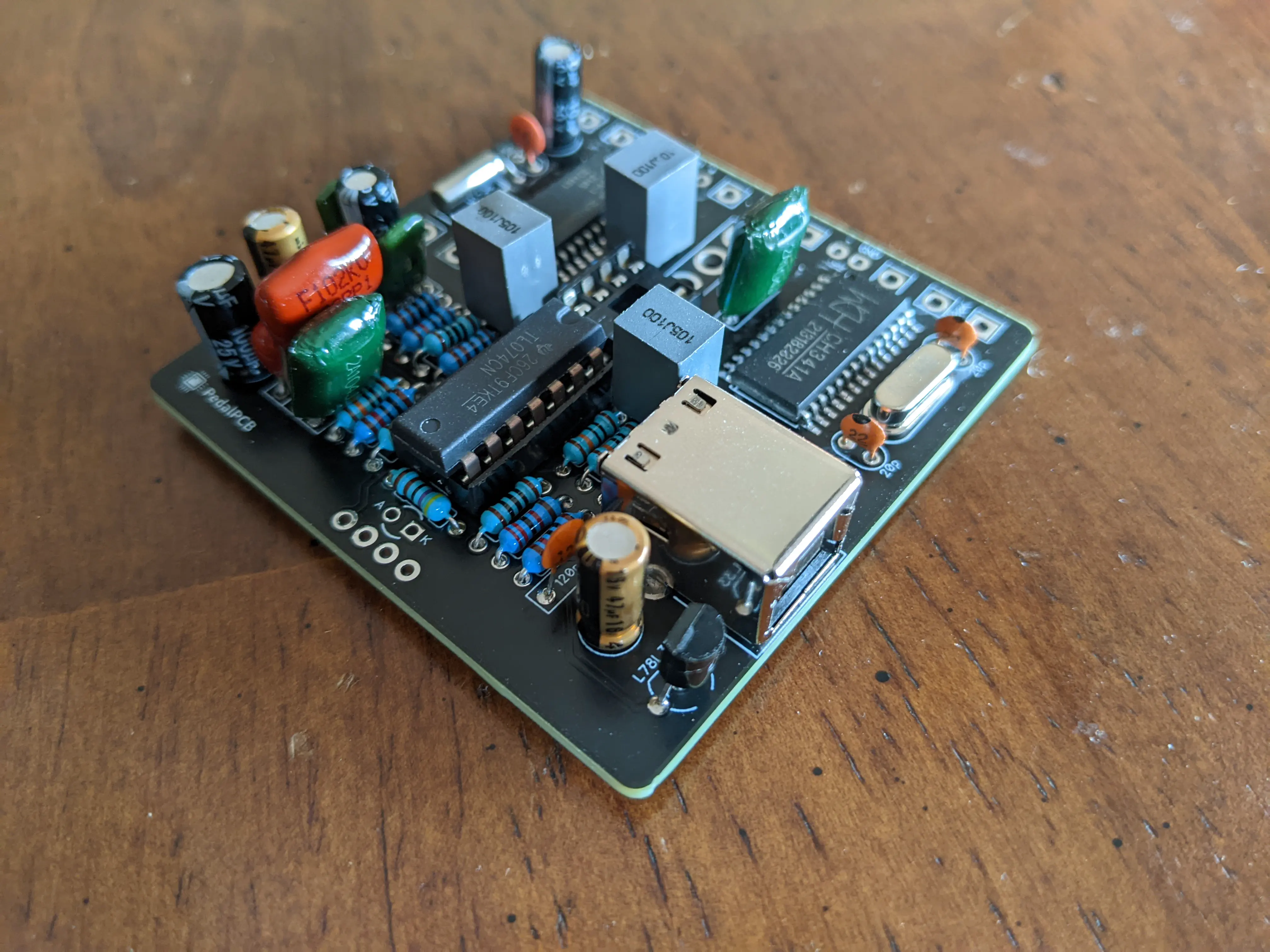 | 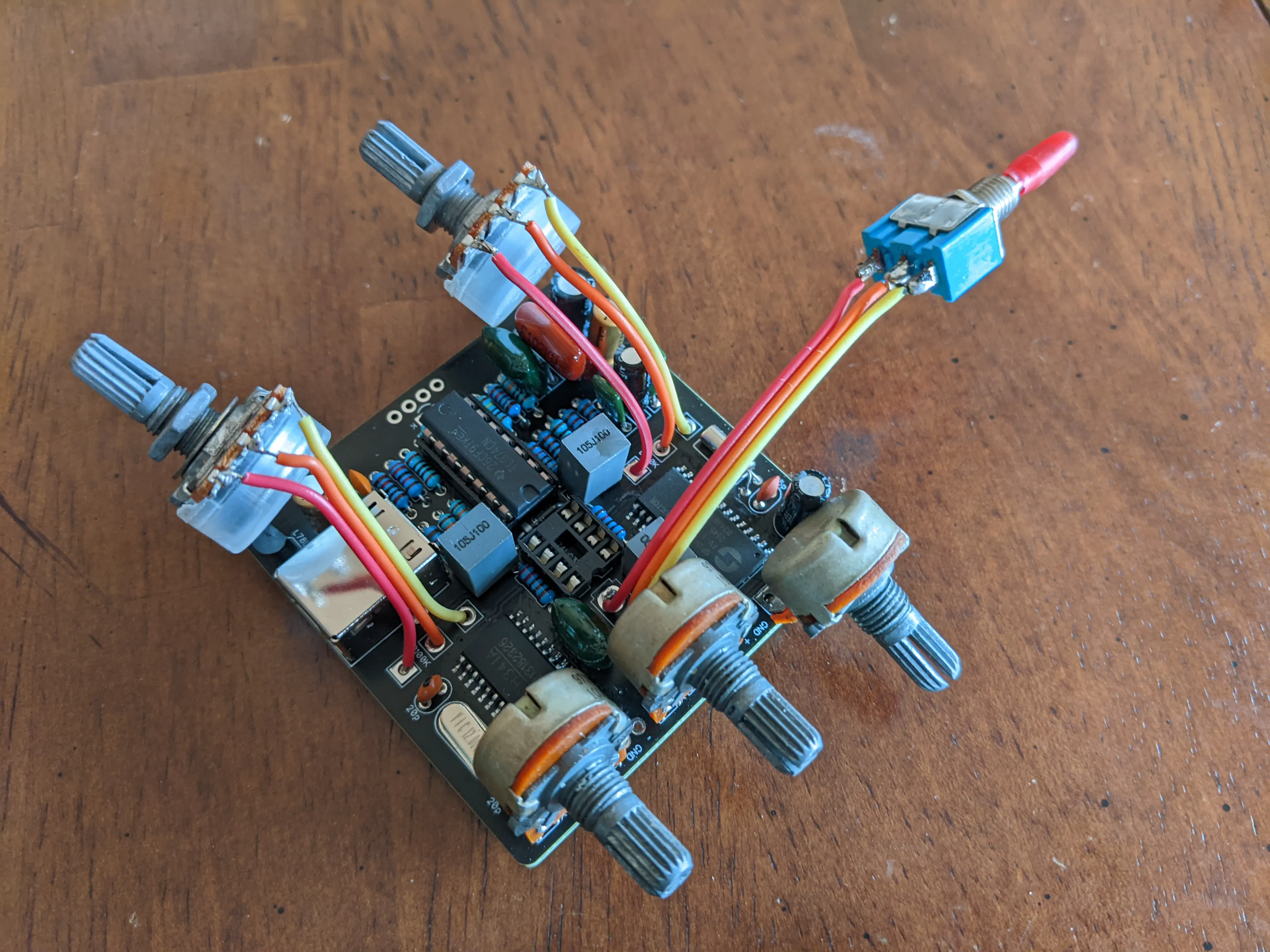 |
 |  |
Now let’s make it make noises.
The Firmware
To write code for the FV-1, we’ll need to speak its language, SPINAsm, but before we get familiar with the specific instructions and syntax, it’s worth a quick overview of the basic principles of assembly.
Registers, Accumulators, and Opcodes
Fundamentally, assembly languages are all about using instructions to modify and move data in and out of registers.
Instructions tell the processor what to do, and they’re made of an opcode (the name of the instruction) and arguments (the parameters used by the instruction).
Registers are memory locations where you can access input data, store intermediate calculations, or send output data. The accumulator3 is a special register that’s used to store data that you’re actively working with.
Hello World
With those definitions in mind, let’s write the simplest FV-1 program possible. It takes the input signal and outputs it unchanged:
;---Hello world!---
LDAX ADCL
WRAX DACL, 0.0
In the first line (after our comment), we use the LDAX instruction to read a value from the ADCL register (left channel pedal input) and store it in the accumulator. On the second line, the WRAX instruction writes the value that we just stored in the accumulator to the DACL register (left channel pedal output) and multiplies it by 0.0 to reset it.
If we ran this program, the FV-1 would read the guitar signal and send it unchanged to the output, once every clock cycle (about 32k times per second).
A Boost Pedal
With a few small changes, we can make this program slightly useful. Instead of outputting the input signal unchanged, let’s boost the gain and then multiply it by a potentiometer value, creating a basic adjustable clean boost pedal.
;---Boost pedal---
RDAX ADCL, 1.9
MULX POT0
WRAX DACL, 0.0
Like LDAX, the RDAX opcode reads a value into the accumulator, but it takes a second argument which the accumulator is multiplied with. Multiplying by 1.9 will give a volume boost. Next, the MULX opcode multiplies the accumulator by a specified value–in this case, the value read from the special POT0 register that stores the output of the first potentiometer on the development board.
The result is that we can adjust the volume of our input signal between 0 and 1.9x the original volume.
A Tremolo Pedal
For the final example, let’s build a basic tremolo. A tremolo is effectively a volume pedal controlled by an oscillator instead of a potentiometer, so this will build off of the previous example while introducing the low-frequency oscillators (LFOs) built-in to the FV-1. This program is a little more complicated, so I broke it into 3 sections.
1. Setup
The LFO will provide an oscillating sine-wave that we’ll use to modulate guitar volume, but it needs to be initialized before we can use it. We can accomplish that with the WLDS opcode. We’ll pass it the name of the LFO we want to initialize, a placeholder frequency value of 0 (we’ll set this later using a potentiometer), and the LFO amplitude that will define the tremolo depth. We’ll use the maximum amplitude of 32767 and control the strength of the effect using the wet/dry mix potentiometer built into the development board.
We only want to run this initialization once at the start of the program, so we’ll put a SKP instruction before it that tells the FV-1 to only execute the next instruction once.
; Setup
SKP RUN, 1
WLDS SIN0, 0, 32767
2. Controls
The LFO is running now, but we’d like to be able to adjust the rate with a potentiometer. We’ll do that by reading POT0 into the accumulator and storing it in the special SIN0_RATE register. To keep the rate in a reasonable range, we’ll use the SOF opcode to multiply the accumulator by 0.5 and add 0.1.
; Controls
LDAX POT0
SOF 0.5, 0.1
WRAX SIN0_RATE, 0
3. Modulation
Finally, we’ll use the LFO to modulate the volume of our input signal. The CHO RDAL opcode reads the LFO into the accumulator. The LFO value is in the range [-1, 1], so the SOF opcode will rescale the accumulator to the [0, 1] range we need. Finally, we can use the familiar MULX and WRAX opcodes to multiply the iwrite_outputnput signal by the re-scaled LFO value and write it to the output.
; Main loop
CHO RDAL, SIN0
SOF 0.5, 0.5
MULX ADCL
WRAX DACL, 0.0
Putting It All Together
Here is our finished tremolo program:
;---Tremolo---
SKP RUN, 1
WLDS SIN0, 0, 32767

LDAX POT0
SOF 0.5, 0.1
WRAX SIN0_RATE, 0

CHO RDAL, SIN0
SOF 0.5, 0.5
MULX ADCL
WRAX DACL, 0.0
Now we just need to get it onto our pedal. The dev board I used has a built-in USB programmer that lets you flash programs to the onboard EEPROM memory, so the process is as simple as 1) assemble the program to binary4, 2) install the necessary software and drivers5, 3) plug the pedal in to USB and power, and 4) flash the program.
How does it sound?
Like a tremolo! Not bad for a day of hacking.
Useful Resources for Learning FV-1
Want to learn more about the FV-1? These were some useful resources I came across.
- The manual and datasheet. Nitty and gritty, but good reference material.
- SpinCAD Designer, an open-source Java GUI for building programs with drag-and-drop blocks. Seeing how block diagrams translate to assembly is very helpful, but the outputs aren’t always optimized.
- The official FV-1 forums. Not very active, but some good threads to read through.
- The Patreon blog of SpinCAD’s designer. Some materials are patron-only and new patrons aren’t being accepted, but there are a lot of good free articles about both SpinCAD and FV-1 programming.
- A great guide for getting started. Basically like what I wrote, but better.
- A high-level guide to designing and building an FV-1 pedal.
Citation needed. ↩︎
After sorting out an LED that I installed backwards, a power jack that needed to be isolated from chassis ground, some 0.1 uF capacitors that were supposed to be 1 uF, and ordering the right potentiometers instead of trying to improvise with ones I had lying around (these fit well if you’re curious). ↩︎
As far as I can tell, 90% of assembly programming is trying to remember what’s in the accumulator at any given time. ↩︎
I used asfv1, which is a handy command-line assembler written in Python. ↩︎
This will depend on operating system. On Windows, I installed the drivers from here and used AsProgrammer for flashing. ↩︎